Notch Filter Schematic Notch Filter Circuit Band Stop Electr
Filtro de muesca (band-stop): ¿qué es? (función de circuito, diseño y Filtre notch également membres ont Notch filter circuits with design details – homemade circuit projects
Notch Filter Circuits with Design Details – Homemade Circuit Projects
Notch filter circuit active stop band electrical4u transfer function Notch filter circuit as an example. Notch integrator sensing ignition
Notch filter (bandstop): what is it? (circuit & design)
Notch filter 60hz circuit twin analogBasic twin-t notch filter circuit Notch filter circuit twin circuits schematic homemade designingFilter notch circuit adjustable diagram simple schematics electronic.
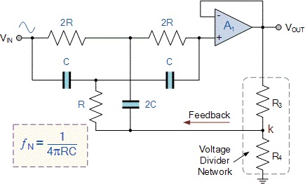
Notch filter circuit band stop electrical4u characteristics transfer function rlcSimple notch filter uses an operational amplifier Notch filter design: a narrow band filter for specific noise attenuationNotch filter: the circuit’s diagram and the design formula – electronic.

Solved in the notch filter circuit shown in the figure,
Electronics & communication projects: helical notch filter schematicNotch filter circuits with design details – homemade circuit projects 60hz notch filterNotch filter design: 37 interesting facts to know – lambda geeks.
Schema filtre notchThe schematic of the sc notch filter Passive notch filter schematicNotch filter schematic diagram.

Notch filter adaptive ccrma
29.85 mhz notch filter schematicSchematic thd notch Notch filter circuit solved frequency response shown figure diagram transcribed problem text been show hasCircuit filter rules at tammy kohler blog.
Filter notch circuit passive band stop bandstop electrical4u transfer functionNotch filter- theory, circuit design and application Notch filter and integrator circuit.Notch filter.

Filter notch circuit operational uses amplifier audio tunable diagram simple applications gr next
Quick and simple notch filter for thd measurements – toli's diyNotch filter circuit theory application amp electrical single op Notch insensitive tolerances ednLc notch filter circuit.
Notch filter 60hz circuit circuitlab better description not60hz notch filter Notch filter (bandstop): what is it? (circuit & design)Notch filter schematic with digital controls w , w , and w and analog.

Op amp active notch filter circuit : configuration and its applications
Notch filter is insensitive to component tolerancesNotch circuits hz Notch filter (bandstop): what is it? (circuit & design)Filter notch diagram formula circuit 2008 eeg schematic november reject arduino.
Proposed notch filter design using the equivalent circuit model: aOp amp Filter notch twin circuit active high hz 60hz audio 60 schematic network simulation op amp filters frequency am circuits amplifierSchematic diagram of the notch filter..

Simple adjustable notch filter circuit diagram
Notch filter: how to make a notch filterFilter notch circuit twin basic band stop filters below theory application reject electrical parallel shown figure .
.


