Not Gate Schematic Not Gate Circuit Diagram And Working Expl
And gate diagram transistor Not gate : circuit, truth table, operation, uses and limitations Not gate : circuit, truth table, operation, uses and limitations
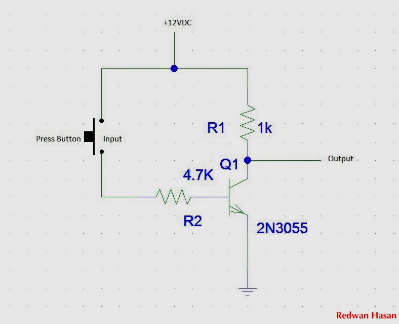
NOT Gate Circuit Diagram and Working Explanation
Gates scheme logic Animated 555 circuit to make patterns in 3*3*3 led cube (part 1 Control 7404, not gate ic, using switch « funny electronics
What is a not gate?
Not gate circuit diagram and working explanationThe not gate Electronics projects: how to create a transistor not gate circuitLogic gate using simulator at mary pilger blog.
Circuit led gate not eevblog forum powerGate not 7404 circuit ic diagram using gates used vcc input output led part arduino working ground timer electronics funny Gate not logic schematic digital pnp inverter rtl case ic symbols its details lowGate not 7404 circuit ic diagram using gates used vcc input output led arduino part working ground electronics funny timer.

The not gate
Simple "not gate" schemeLogic not gate tutorial with logic not gate truth table Gate not circuit diagram input power through circuitdiagram button explanation connected thenGate transistor.
Simple not gate circuitNot gate circuit diagram and working explanation Draw the transistor based circuit diagram for not gate and also giveSchematic diagram of xor gate.

Gate not circuit logic gates input operation analysis diode digital
Gate not circuitWhat is a not gate? And or not gate circuit diagramLogic and gate working principle & circuit diagram.
Rgb led circuitGate valve schematic What is not gate inverter, not logic gate inverter circuit using transistorDigital logic not gate (inverter), its symbols, schematics & ic details.

Transistor not gate logic gates electronics digital circuit using switch table truth circuits switches tutorial off moteino base doorbell input
Gate not circuit transistor logic inverter using truth tableGate ic not circuit 74ls04 pinout logic diagram xnor gates working input chip nor hex circuitdigest electronic electrical engineering diagrams Gate not circuit switch switching lamp open logic symbol when will illustrates glow go off figure게이트가 아닌 것(인버터)-전자-fmuser fm/tv 방송 원스톱 공급업체.
Not gate circuitNot gate circuit diagram Simple inverter circuit diagram downloadWorking of not gate using transistor.

Simple not gate circuit
Gate not symbol logic circuit known circuitglobeCircuit diagram not gate using transistor .
.


